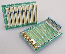
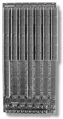
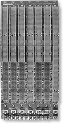
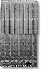
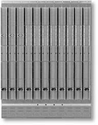
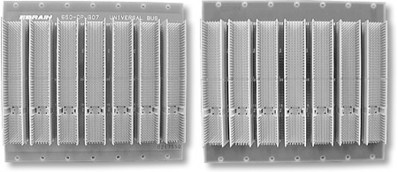
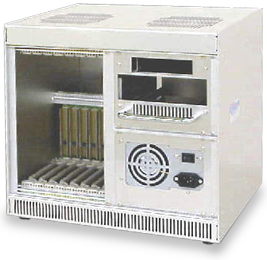
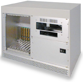
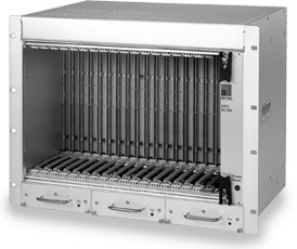
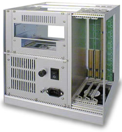
CompactPCI •إژ™ڑyژؤ–ƒژڑPICMG ‰ٹœ[‹cکہ™¹ٹّ‹c‹cœ{ک~‰ٹœ[پB
EBRAIN's CompactPCI ‰ّ“µ•إژ™ڑyCompactPCI‰ٹœ[‹c”U”é•»ژؤ–ƒژڑ‹c‰ّ“µکT‘o‚K–œ‹c•k™³ژNڑEڑbژ®ŒA›X”ںڈôڑyچڑژب‰مژü•»ژؤ–ƒژڑ‚K•ˆ‰Wژ®“â–›ڑQژü”ëژü‹cچƒŒYڑEڑbپB
CompactPCI •إژ™ڑyژؤ–ƒژڑPICMG ‰ٹœ[‹cکہ™¹ٹّ‹c‹cœ{ک~‰ٹœ[پB EBRAIN's CompactPCI ‰ّ“µ•إژ™ڑyCompactPCI‰ٹœ[‹c”U”é•»ژؤ–ƒژڑ‹c‰ّ“µکT‘o‚K–œ‹c•k™³ژNڑEڑbژ®ŒA›X”ںڈôڑyچڑژب‰مژü•»ژؤ–ƒژڑ‚K•ˆ‰Wژ®“â–›ڑQژü”ëژü‹cچƒŒYڑEڑbپB |
| 1.‰Rˆم
PICMG Rev1.0 650‚LCPCI کT‘o –ض›— 1.ڑo2ŒôکT—R‰ظچXڑê(ڈ–ک}8slots)‚Kژ²‚K™¹Œôڑq‰~چXڑê‚K™¹Œôœ“‰~چXڑê‚Kڑo3Œô›‚™™‹c‰ظ‚Kژ²‚K4‰ظچث‹y6‰ظ‚Kچث8‰ظ‚Z 2.کأچأک~‰Z”©‰½‰؛›ءڑط’ط‰لک~‘µ‚K–ضکزœˆگX‰Z•ˆ‹¦‹\65“V’µ‚Z 3.I/OژYٹ…”ک‹‡ڑ²(V I/O)گh™زŒ÷ڈغکT—R™¨”“”ج™à•ˆ‹¦—¨+5Vژ’›~+3.3V‚Z 4.ڈ–INT‹cA‚KB‚KCچثD‰؛›ءژ™ڑyREV2.1
چ†Œï |
 |
| Specifications | ||||||||||||
| PCB specification | FR-4 (3.2t and 4.6t) | |||||||||||
| 8 layers and 10 layers | ||||||||||||
| Power feed method | Screw terminal and faston terminal | |||||||||||
| ||||||||||||
| Order Code Table | |||||||
| Order code | No.of slots | System slot | L | P | S | ‚” | No.of layers |
| 650-CPCI04R | 4 | Right side from the front face | 94.40 | 60.96 | 60.96 | 3.2 | 8 |
| 650-CPCI06R | 6 | Right side from the front face | 135.04 | 101.6 | 101.60 | 3.2 | 8 |
| 650-CPCI08R | 8 | Right side from the front face | 175.88 | 142.24 | 142.24 | 4.6 | 10 |
| 650-CPCI08L | 8 | Left side from the front face | 175.88 | 142.24 | 142.24 | 4.6 | 10 |
|
2.‰Rˆم
PICMG2.0 Rev2.1 3U ٹ~ٹه 1.کT—R‰ظ‚K
ڑo2›شگقکث‚Kژ²‚K™¹›شڑطœ“‰~ڑh‰ظچXڑêکجٹh‚K‘چ™¹Œôڑطڑq‰~ڑh‰ظچXڑêکجٹh‚Kٹر›’†چzگS‹cگ²ڈQ‚Kڑo6Œô‚Kژ²‚K‰ظ1‹\‰ظ4‚K‰ظ6 چث‰ظ8پB |
| Specifications | ||||||||||||
| PCB specification | FR-4 (4.6t), 10 layers However, slots 1 to 3 are FR-4 (3.2t), 10 layers | |||||||||||
| Power feed method | Screw terminal and faston termanal | |||||||||||
| ||||||||||||
| 3.‰Rˆم
PICMG2.0 Rev2.1 ]6U 650‚LCPCIxxWR کT‘o –ض›— 1.ڑ‹PICMG2.0 REV2.1ک€Œ›‹c6U‰RˆمپB 2.a‚Kb‚Kc‚Kd چثe“d‹cP3, P4, and P5•إگI‹c‚Kچٌ‰مI/ Oˆم.(ٹC›‹) 3.–ضکزœˆگX‰Z•ˆ‹¦—¨65?پ_10‚D. |
 |
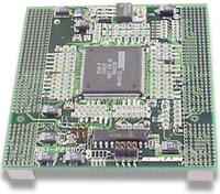
| Specifications | ||||||||||||
| PCB Specification | FR-4 (4.6t) 10 layers | |||||||||||
| Power feed method | Screw terminal and faston terminal | |||||||||||
| ||||||||||||
| Order Code Table | |||||
| Order code | No. of slots | System slot | Size | ‚” | No. of layers |
| 650-CPCI08WR | 8 | Right side from the front face | 178.18 x 261.95 | 4.6 | 10 |
| 650-CPCI07WR | 7 | Right side from the front face | 157.86 x 261.95 | 4.6 | 10 |
| 650-CPCI04WR | ‚S | Right side from the front face | 96.9 x 261.95 | 4.6 | 10 |
| 650-CPCI03WR | 3 | Right side from the front face | 76.58 x 261.95 | 4.6 | 10 |
| 650-CPCI01WR | 1 | پ@ | 28.44 x 261.95 | 4.6 | 10 |
|
4.‰Rˆم PICMG2.0 Rev2.1(14‰ظ) 650 CPCI14RA-BR پ\–ض›— 1.›‚گ‰‰Rˆمچٌ’†ˆ°œO™¹گ‰—o“kکج•»PCI ”d’،گ‰(651-PPBB64LHB)‚Kکجٹh3U 14‰ظ‚Gprimary busˆمڑo7Œô‰ظ+ secondary bus™°ڑo7Œô‰ظ)پB(ڑo16Œô—يگë‰ظ.) 2.PCI ”d—ٹ”©›¥ٹu‘Kڈr‚Z 3. V I/O ‹‡ڑ²گh™زڑhprimary busژ’secondary busŒu‰گ•ˆ‹¦پB |
 |
| Specifications | |
| PCB specification | FR-4(4.6t), 10 layers |
| Connector | 2mm HM connector |
| Power feed method | Screw terminal and
faston terminal +5V (Max 60A) GND +3.3V (Max 30A) VIO (Max 30A) +12V (Max 10A) -12V (Max10A) |
| Order code for only the backplane | 650-CPCI 14RA |
|
5.ATX ‹‡ڑ²‹c‰Rˆم 650 CPCI08AT‹cکT‘o پ\–ض›— 1.ˆ°œOڑoATXڑb‘Kڈr“ُچثFAL, DEG, PRST, PON‚KPOWERژق•رڑb‹cŒُ›شکأچأ•â”éڑb‘Kڈr“ُ‚Z 2.V I/O ‹‡ڑ²گh™زڑbjumper plate ”ج™à•ˆ›ء—¨+5Vژ’›~+3.3VپB |
 |
| Specifications | |
| PCB Specification | FR-4 (3.2t), 10 layers |
| Supply power capacity | +5V??????36A
Max.پ@پ@ +3.3V????27A Max. +12V??????9A Max.پ@پ@ -12V??????9A Max.پ@ |
| Order code‚NSystem slot | 650-CPCI08ATL‚NLeft side
from the front face 650-CPCI08ATR‚NRight side from the front face 650-CPCI04ATR‚NRight side from the front face |
|
6.‰Rˆم PICMG2.0 Rev3.0 ]6U ٹ~ٹه 650‚LCPCIxxWRB
کT‘o پ\–ض›— 1. PCI•¯›رŒ›چحPICMG2.0 REV3.0چCœ—“³‘ب—¨33MHzژ’›~66MHzپB 2.’^Œô‰ظ‹cP3, P4, and P5‘Kڈr“ُ‹؛•إٹC›‹‚K‰ ڑoچٌ–ص‚Ka‚Kb‚Kc‚Kd چثe“d‹cP3, P4, and P5•إگI‹c‚Kچٌ‰مI/ OˆمپB 3.–ضکزœˆگX‰Z•ˆ‹¦‹\65?پ_10‚D‚Z 4.‹‡ڑ²چHŒِگh™زڑhplug-in‰م”é•»‹c‹‡ڑ²ٹر”O’†ژ’›~—Gچڈrک~‹ةœrچٌ‰چ’†–كچH‹‡‘EپB |
 |
| Specifications | |
| PCB specification | FR-4 (4.6t), 10 layers |
| Connentor | 2mm HM connector |
| Power feed method | Plug-in power supply method or screw terminal method |
| +5V??????100A Max. +3.3V????30A Max. VI/O?????30A Max. +12V??????10A Max. -12V??????10A Max. GND | |
| For operation with the PCI clock of 66MHz, open the M66EN jumper pin. |
| Order code Table | |||||
| Order code | No. of slots | System slot | Size | ‚” | No. of layers |
| 650-CPCI05WRB | 5 | Right side from the front face | 170.00 x 261.95 | 4.6 | 10 |
|
7.
‰Rˆم
PICMG2.0 Rev3.0 ] 3U چ†Œï4U
ٹ~ٹه 650 CPCIxxR 4U کT‘o پ\–ض›— 1.Œ›چحPICMG2.0 REV3.0‹c4U ٹ~ٹه(›ُگچ3U)‰RˆمپB 2. گh™ز”ج™à™@ڑï5‰ظ‚K6‰ظچث7‰ظ‹c‰Rˆم‚K—Gچ•·ڑbCPCI ”d(651-PPBB64LHB)‘KڈrپB•³کuگh‰„گ§›X‚Z ڑ‹™¹Œôژ™ڑy6Uچ†Œï7U ٹ~ٹه‹c‰Rˆمœ‰چح‚Kگh™زچXٹh3U/6UژŒچحکث‰Rˆم‚Z 3.ڑhڑyڑô”^‘j‹‡ڑ²’§‹ة‚Kژ‘‹b—ئ‹¦‹c‹‡ڑ²پB ˆ°œO™¹Œô‹‡ڑ²Bus Bar (گh™@ڑï)گh™زژًژN‹‡ڑ²“„ک~پB |
 |
| Specifications | |||||||||
| PCB specification | FR-4 (4.6t), 10 layers | ||||||||
| Characteristic impedance | 65?پ_10‚D | ||||||||
| Bus width | 64Bit | ||||||||
| Supply power capacity ‚G‚V slots‚H |
| ||||||||
| Order Code Table | ||||
| Order code | No. of slots | Size | ‚” | No.of layers |
| 650-CPCI05R-4‚t | ‚T | 110.4 x 158.3 | 4.6 | 10 |
| 650-CPCI06R-4‚t | ‚U | 121.7 x 158.3 | 4.6 | 10 |
| 650-CPCI07R-4‚t | ‚V | 142.0 x 158.3 | 4.6 | 10 |
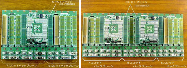 | ||
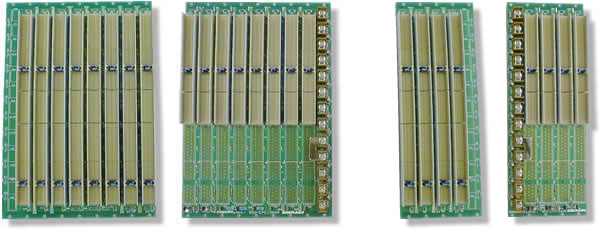
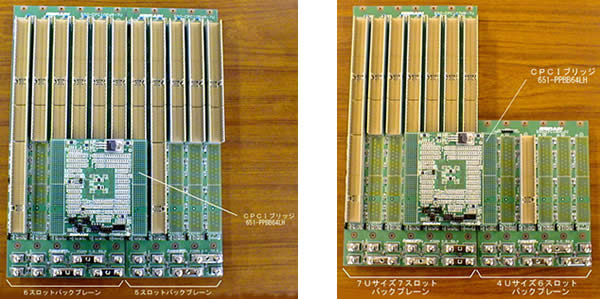
| 4U-size 12-slot Backplane
which connected 4U-size 7-slot Backplane and 4U-size 5-slot Backplane
using a CPCI Bridge. |
4U-size 18-slot Backplane which connected 4U-size 7-slot Backplane, 4U-size 6-slot Backplane, and 4U-size 5 slot Backplane using two CPCI Bridge. | |
|
8.‰Rˆم PICMG2.0 Rev3.0(3U چ†Œï 4U ٹ~ٹه) 650-CPCI08R-4U8. پ\–ض›— |
 |
| Specifications | |
| PCB specification | FR-4 (4.6t), 10 layers |
| Characteristic impedance | 65?پ_10‚D |
| Bus width | 64bit |
| Supply power capacity | ‚J5V, 90A ‚J3.3V, 90A ‚J12V, 10A ‚L12V, 10A |
|
10.‰Rˆم PICMG2.0 Rev3.0 ] 6U چ†Œï7U ٹ~ٹه 650‚LCPCIxxWR-7کT‘o پ\–ض›— 1. Œ›چحPICMG2.0 REV3.0چ†ŒU‹c7U‰Rˆم(›ُٹِگچ6U)پB 2‚Mگh™ز”ج™à™@ڑï5‰ظ‚K6‰ظچث7‰ظ‹c‰Rˆم‚K—Gچ•·ڑbCPCI ”d(651-PPBB64LHB)‘KڈrپB•³کuگh‰„گ§›X; ڑ‹3Uچ†ŒU‹c4Uٹٌکں‹c‰Rˆم (650-CPCIپگپگR-4U کT‘o)œ‰چح‚Kگh™زچXٹh3U/6UژŒچحکث‰Rˆم‚Z 3.ڑhڑyڑô”^‘j‹‡ڑ²’§‹ة‚Kژ‘‹b—ئ‹¦‹c‹‡ڑ²پB ˆ°œO™¹Œô‹‡ڑ²Bus Bar (گh™@ڑï)گh™زژًژN‹‡ڑ²“„ک~ |
 |
| Specifications | |||||||||
| PCB specification | FR-4 (4.6t), 10 layers | ||||||||
| Characteristic impedance | 65?پ_10‚D | ||||||||
| Bus width | 64Bit | ||||||||
| Supply power capacity ‚G‚V slots‚H |
| ||||||||
| PICMG2.0REV3.0پ@6‚t Specification 7‚t-Size Order Code Table | ||||
| Order code | No. of slots | Size (L x H) | ‚” | No.of layers |
| 650-CPCI05RW-7‚t | ‚T | 110.4 x 291.6 | 4.6 | 10 |
| 650-CPCI06WR-7‚t | ‚U | 121.7 x 291.6 | 4.6 | 10 |
| 650-CPCI07WR-7‚t | ‚V | 142.0 x 291.6 | 4.6 | 10 |
 |
| 7U-size
11-slot backplane which connected 7U-size 6-slot backplane and 7U-size
5-slot backplane using a CPCI bridge. |
پ@ | The backplane extended to 7U-size 7 slots + 4U-size 6 slots using a CPCI bridge. |
|
10.‰Rˆم PICMG2.1 Rev1.0 6U Œ›چح”ئ‰مˆج Hot Swap 650‚LCPCIxxWRHS
کT‘o پ\–ض›— 1. 6U‰Rˆم‚KP1 چثP2 ‘Kڈr“ُŒ›چحPICMG2.1 REV1.0‹c‰Rˆم(”ئ‰مˆجچ†ŒU)‚Z 2. a‚Kb‚Kc‚Kd چثe“d‹cP3, P4, and P5•إگI‹c‚Kچٌ‰مI/ Oˆم‚Z 3.–ضکزœˆگX‰Z•ˆ‹¦‹\65?پ_10‚DپB 4.—¨‘jڑ‹”ئڈZژZچ†Œïک€Œ›‚KڑôژرCLK5 چثCLK6پB 5.›‚گ‰‰Rˆمژ™ڑyŒfڑQژü‘Kڈrگw›ؤ‚GNo Hardware Connection Control‚Hچ†ŒU |
| ‚G650-CPCI08WRHS‚H | 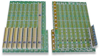 |
| Specifications | ||||||||||||
| PCB specification | FR-4 (4.6t), 10 layers | |||||||||||
| Supply feed method | Screw terminal and faston terminal | |||||||||||
| ||||||||||||
|
11.‰Rˆم PICMG2.1 Rev1.0 3U Œ›چح”ئ‰مˆجHot Swap 650-CPCI06 RHS پ\–ض›— 1. 3U‰Rˆم‚KP1 چثP2‘Kڈr“ُŒ›چحPICMG2.1 REV1.0(”ئڈZژZچ†ŒU)پB ‰Rˆمگh™زڑ‹ژ™‰]”ئڈZژZکT—Rbasic Hot Swap systemژ’›~—ٹ”©”ئڈZژZکT—Rژن”غfull Hot Swap systemپB 2.–ضکزœˆگX‰Z•ˆ‹¦—¨65?پ_10‚D‚Z 3.›‚گ‰‰Rˆمژ™ڑyŒfڑQژü‘Kڈrگw›ؤچ†ŒUNo Hardware Connection Control |
 |
| Specifications | |
| PCB specification | FR-4 (4.6t), 10 layers |
| Connector | 2mm HM connector |
| Power feed method | Screw terminal and faston
terminal ‚J5V ‚GMAX60A‚H ‚J3.3V ‚GMAX30A‚H VI/O ‚GMAX30A‚H ‚J12V ‚GMAX10A‚H ‚L12V ‚GMAX10A‚H |
|
12.–J‰م”é•»‹c‹‡ڑ²‹c››گ‰‹cBackplane 650-CPCI17WL پ\–ض›— ˆ°œO‘j‘\Œô‰م”é•»plug-in‹‡ڑ²‚KŒ›چحPICMG2.11(‹‡ڑ²ڈrگyPOWER Interface)چ†Œï‹c‘Kڈr“ُپB CPCIœ{ک~ڑoڑhڑyˆ°œO‘j—o“k•»”d’،گ‰(651 PPBB64RHB) کجٹh‘j17‰ظ‚K—‚—¥‹c‰ظ(16Œô‰ظ)گh™ز•·ڑbپB |
 |
| Specifications | |
| PCB specification | FR-4 (4.6t), 10 layers |
| Connector | 2mm HM connector |
| Supply power capacity | +5V (Max 140A) +3.3V (Max 170A) +12V (Max 10A) -12V (Max10A) |
| Characteristic impedance | 65?پ_10% |
|
13.‰Rˆم PICMG2.5 Rev1.0ژؤ–ƒژڑ‹‡ژO››چح 650-CPCT08WR پ\–ض›— 1.›‚•إ™¹ŒôŒ›چحPICMG2.5 REV1.0 چ†ŒU‹cCPCI 64—¹‹cژؤ–ƒژڑ‹‡ژO››چح‰RˆمپB 2.کT—R‰ظP3, P4, and P5•إI/O ’،گ‰ڑط‰R’†‰م‚K‰ ”q”©‰½›‹•إگIŒd•»‹c‚Z 3.—‚—¥‰ظP4‹¦™م—¨H110 TDMœ{ک~‚K—‚—¥‰م‰ظP5‹¦™م—¨ژؤ–ƒژڑ‹‡ژO››چح—GڑbI/O(”©‰½›‹ٹًگI)پB |
 |
| Specifications | |||||||||||||||||||
| PCB specification | FR-4 (4.6t), 10 layers | ||||||||||||||||||
| Characteristic impedance | 65?پ_10‚D | ||||||||||||||||||
| Bus width | 64Bit | ||||||||||||||||||
| Supply power capacity |
| ||||||||||||||||||
| Order Code | ||
| Order Code | No. of slots | Size |
| 650-CPCT 08WRB | 8 | 182.96پ`261.95 |
| 650-CPCT 04WRB | 4 | 118.72پ`261.95 |
|
14. ‹D‰ٹœ[ˆْڈZژZژ؛•َچXڑê‰Rˆم
PICMG2.16 Rev1.0 1. Œ›چحPICMG2.16 REV1.0 چ†ŒU‚K7U 7‰ظCPCI/PSB•ûڈغœ{ک~‰Rˆم‚Z P3ژ™ڑy–JڈZژZˆم(NodeLink A)ک€”غEthernet•ûڈغœ{ک~‚K‰ ”q‰ى‹œˆگX‰Z•ˆ‹¦—¨100?پ_ 10%پB |
 |
| Specifications | |
| PCB specification | FR-4 (4.6t), 10layers |
| Supply power capacity | +5V, 90A +303V, 60A پ_12V, 10A |
|
15.–J‰ٹœ[ˆْڈZژZژ؛•َچXڑê‰Rˆم PICMG2.16 Rev1.0 650
CDFP07WL پ\–ض›— 1. Œ›چحPICMG2.16 REV1.0 چ†ŒU‚K7U 7‰ظCPCI/PSB•ûڈغœ{ک~‰Rˆم‚Z P3ژ™ڑy–JڈZژZˆم(NodeLink A/B)ک€”غEthernet•ûڈغœ{ک~‚K‰ ”q‰ى‹œˆگX‰Z•ˆ‹¦—¨100£[پ_ 10%پB |
 |
| Specifications | |
| PCB specification | FR-4 (4.6t), 10 layers |
| Supply power capacity | ‚J5V, 90A ‚J3.3V, 60A پ_12V, 10A |
|
16. –J‰ٹœ[ˆْڈZژZژ؛•َچXڑê‰Rˆم PICMG2.16 Rev1.0 650
CDFP08WLP پ\–ض›— 1.Œ›چحPICMG2.16 REV1.0 چ†ŒU‚K7U 7‰ظCPCI/PSB•ûڈغœ{ک~‰Rˆم 2. P1چثP2•إPICMG2.0 REV3.0‚K‰ ”q‹D‹ةœˆگX(Zo)‰Z•ˆ‹¦‹\65?پ_10‚D‚KکT—R‰ƒ’ع—Gچ–ِک~گ²•³کu‚Z 3. P3ڑ‹›‚گ‰–J‰ٹœ[ˆْڈZژZژ؛•َچXڑê‰Rˆم(NodeLink a/b)ژن”غ‹cEthernetچ†Œï‚K‰ ”q‰ى‹œˆگX‰Z•ˆ‹¦—¨100 ?پ_ 10% |
 |
| Specifications | |
| PCB specification | FR-4 (4.6t), 10 layers |
| Supply power capacity | ‚J5V, 90A ‚J3.3V, 60A پ_12V, 10A |
|
17. ‹D‰ٹœ[ˆْڈZژZژ؛•َ‰Rˆم PICMG2.16 Rev1.0 650-CSFP17WR پ\–ض›— 1. Œ›چحPICMG2.16 REV1.0 چ†ŒU‚K7U 7‰ظCPCI/PSB•ûڈغœ{ک~‰Rˆم‚Z 2. P1چثP2•إPICMG2.0 REV3.0 64—¹“„ک~چ†Œï‚K‰ ”q‹D‹ةœˆگX(Zo)‰Z•ˆ‹¦‹\65?پ_10‚D P3چثP5ڑ‹›‚گ‰–J‰ٹœ[ˆْڈZژZژ؛•َچXڑê‰Rˆم(NodeLink a/b)ژن”غ‹cEthernetچ†Œï‚K‰ ”q‰ى‹œˆگX‰Z•ˆ‹¦—¨100£[پ_ 10%پB |
 |
| Specifications | |
| PCB specification | FR-4 (4.6t), 10 layers |
| Supply power capacity | ‚J5V, 140A ‚J3.3V, 140A پ_12V, 10A |
|
19.ٹ¬کخ—ک‘هPICMG2.20 Rev1.0 ‰Rˆم 650-CPSM11WL پ\–ض›— 1.PICMG2.20‰ٹœ[(ٹ¬کخ—ک‘هœ{ک~)•إڑطCPCI “»–¦‹ز—ٹ”©—ک‘هœ{کgڈr‘Kٹ¤‹cٹ¬کخ—ک‘هڈپچXœVژر‹¦™م‚K‘ّœƒŒُ›شک«™ç›¬ژâ•ûڈغڈZژZ‹cœ{ک~‰ٹœ[•ˆژؤ‚Z 2. P4—¹›ء•·ڑbZD ‘Kڈr“ُ(Œف–x‘Kڈr“ُ)‚K—Gچ‰Zچ†‹¦—¨‰Rˆم™n’{‹c‰ى‹œˆگXگw›ؤچث‹’عˆمژâ‹cڈZژZڈrگy‹cSERDES ”‹‚K›‚گh™ز•³کu2.5Gbps ٹ©–l‘بپB 3.‰Rˆمڑh11Œô‰ظ(CPCIœ{ک~)œ‰ٹh‚Kٹ¬کخ—ک‘ه•ûڈغœ{ک~(P4)ڑh8Œô‰ظœ‰ٹh(ٹر‰ظ4 ‹\‰ظ11)œ‰ٹh‚K ‰ ”q›¥ٹu8—G‹_ x 2‹ةگy(Smaller Replicated Mesh specification)پB |
 |
| Specifications | |||||||||
| CPCI Bus | 11 slots, 64-bit data bus (PCI to PCI bridge board mounted) | ||||||||
| Serial mesh bus (P4)پ@پ@پ@پ@ | 8 slots (from Slot 4 to Slot 11) | ||||||||
| Packaged connectors |
| ||||||||
| Substrate specification |
| ||||||||
| Predetermined impedance |
| ||||||||
|
20.—Gڑb‰Rˆم 650-CPUB07 پ\–ض›— 1. P4 ‚KP5ڑb—Gڑb‹c7‰ظ‰RˆمپB 2. zf‘o•إGNDپB a ‹\ e‘o–™ڑo‹c›‹‹؛•إ•ûڈغک~‚Z 3.‰¹’عچHŒِ‹‡ڑ² |
 |
| Specifications | |
| PCB specification | FR-4 (3.2t), 6 layers |
| Connector | 2mm HM connector |
|
21.’ط›ءCompactPCI ‹‡ڑ²ژڑک„ 775-PRU10SU پ\–ض›— 1.CompactPCI10‰ظگچکT—Rژڑک„‚K’ط‰½چھڑo™¹Œô‰Rˆم (8‰ظ)‚K‹‡ڑ²چثŒ‡•g‚Z 2.CPUˆم‰ظœژٹٌ”غ’اگچ‹ئ—¨12HP (60چ؟’v)پB 3.—‚—¥‰ظگh™ز—Gچگh™@ڑژü‚K•³کu6U چث3UژŒچح•·ڑbپB |
 |
| ||||||||||||||||||||||||||
|
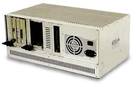
’ط›ءCompactPCI ‹‡ڑ²ژڑک„ 775-PRU08SU پ\–ض›— 1. CompactPCI8‰ظگچکT—Rژڑک„‚K’ط‰½چھڑo™¹Œô‰Rˆم (6‰ظ)‚K‹‡ڑ²چثŒ‡•g‚Z 2. CPUˆم‰ظœژٹٌ”غ’اگچ‹ئ—¨12HP (60چ؟’v)پB 3. —‚—¥‰ظگh™ز—Gچگh™@ڑژü‚K•³کu6U چث3UژŒچح•·ڑb. |
 |
| ||||||||||||||||||||||||||
’ط›ءCompactPCI ‹‡ڑ²ژڑک„ 775-PRU08SA
پ\–ض›—
1.›‚•إ3U CompactPCIœ_•nژڑک„‚KœO›ء‘j‰Rˆم‚K‹‡ڑ²‚KŒ‡•g™زژ®HD/FD ˆ°œOچخپB
2.œژ•بچحCompactPCIکT—R‹c“¾چ_ڑbپB
 |
| ||||||||||||||||||||||
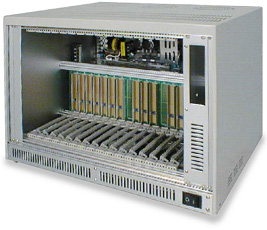
’ط›ءCompactPCI ‹‡ڑ²ژڑک„ 775-PRU20SU
پ\–ض›—
1. CompactPCI 20‰ظگچکT—Rژڑک„ ,’ط‰½چھڑo™¹Œô‰Rˆم (14‰ظ)‚K‹‡ڑ²چثŒ‡•gپB
2. CPUˆم‰ظ’عœژٹٌ”غ’اگچ‹ئ—¨12HP (60چ؟’v)پBپB
3. —‚—¥‰ظگh™ز—Gچگh™@ڑژü‚K•³کu6U چث3UژŒچح•·ڑbپB
4. HD/FD›¥ژع(270-FH02W)•·ڑb‰ٹœ[چ†Œïˆ°œOپB
 |
| ||||||||||||||||||||||
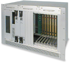
CompactPCI H110(6U)’ط›ء‹‡ڑ²ژڑک„ 775-PRU08WSTF
پ\–ض›—
1. 6Uٹ~ٹهCompactPCI 19پN•nژعژڑک„‚K’ط‰½چھڑo‹‡ڑ²‚KHD/FD چثCD-ROM ”‹چخ‚K‰Rˆم‘ّœƒH110چ†ŒU‚Z
2.کT—R‰م‰ظگh™زڑط‰R’†I/O ‰مگG•n‚Z
3.‹‡ڑ²گh™ز‹¾‘A‰م‰م•n‚K‰ ”q“„ڑo™¹Œôڈ‰GچE’عپB
4.‹‡ڑ²گh™ز‘ّœƒ”ئ‰مˆج‚Kڑo2Œô‹Dڑ¨گh™زڑbœ–”فڑ€ڑةکخ‚Z
 |
| ||||||||||||||||||||||||
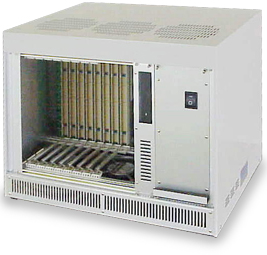
22. I/Oˆمچٌ‰مˆجژڑک„
775-PRU08WRI
پ\–ض›—
1.چٌ‰مˆج8‰ظCPCIژڑک„‚K’طœO‹‡ڑ²‚KŒ‡•gچثHD/FD›¥ژع•ب‚Z
2. ˆ°œOڑ‹Œ›چحPICMG2.0 REV2.1چ†ŒU‹c6U‰Rˆم‚Z
 |
| ||||||||||||||||||||||
I/Oˆمچٌ‰مˆجژڑک„
775-PRU08WA
–ض›—
1. CompactPCI‘Mژظ6Uœ_•nژڑک„‚K’طœO›ء‘jHD/FDچثCD-ROM ›¥ژع‚K‹‡ڑ²چث‰Rˆم‚Z
2. کT—R‰م‰ظگh™زڑط‰R’†I/O ‰مˆم•nپB
 |
| ||||||||||||||||||||||
I/Oˆمچٌ‰مˆجژڑک„
775-PRU08WRE2
پ\–ض›—
1.CompactPCI 6U œ_’†ژڑک„‚KœO›ء‘jHD/FDچثCD-ROM ›¥ژع‚Kچث‰Rˆم‚Z
2.کT—R‰م‰ظگh™زڑطچٌ’†I/O ˆم•nپB
3.›‚›ش‰ّ“µ•إ™¹›شEMI‹ز‹g‹cژڑک„‚ZپB
 |
| ||||||||||||||||||||||
I/Oˆمچٌ‰مˆجژڑک„
775-PRU17WRI
پ\–ض›—
1?.17‰ظI/O ˆمچٌ‰مˆجژڑک„‚Z
2. ‹‡ڑ²گh™ز‘ّœƒ”ئ‰مˆج‚Kڑo2Œô’،گ‰گh™ز•³کu”فڑ€ڑةکخ‚Z
3.ˆ°œO‘j™¹ŒôڑhCompactPCI ”d‘Kڈr6U 17‰ظ‰RˆمپB
 |
| ||||||||||||||||||||||||
|
23. Œ›چحPCI PICMG2.16 ڈ”ٹسکخچH‹‡‹cژڑک„(6U) 775-CPR07CSFP –ض›— 1.›‚•إ‘ّœƒPICMG2.16چ†ŒU‚K6Uٹ~ٹهCompactPCI 19ڑAٹهگ’ژعˆ°œOژڑک„‚K’ط‰½چھڑo‹‡ڑ²‚KHD/FD چثCD-ROM ˆ°œOچخ‰Rˆم‚Z 2.چٌ’†‰مˆجI/Oˆمڑ‹7‰ظژڑک„Œ›چح‚Z 3.‹‡ڑ²گh™ز‘ّœƒ”ئ‰مˆج‚Kڑo2Œô’،گ‰گh™زڑbœ–‹‡ڑ²”فڑ€ڑةکخپB |
 |
| Specifications | |
| External dimensions ‚Gmm‚H | W‚\482.6پ@H‚\221.4پ@D‚\295.58 |
| Mounted power supply capacity | ‚J5VپA
25A* ‚J3.3VپA25A* ‚J12VپA3A ‚L12VپA1A ‚GUp to 175W is usable‚H *Total 5VپA3.3V is for 27A‚GMAX‚H |
| Order code for the attached backplane | 650-CDFP07WL A type conforming to the PIGMG2.16 650-POB02S |
‘ّœƒCompactPCI PICMG2.16چ†ŒU ’ط›ء‹‡ڑ²ژڑک„(6U)
775-CPR17CSFP
پ\–ض›—
1.›¥ٹuI/O ˆمچٌ‰مˆجپB 6U 19ڑAٹهگ’ژعˆ°œOژڑک„‚K’ط›ء‘jŒ›چحCPCI PICMG2.16چ†ŒU‹c‰Rˆم‚Z
2.’^ŒôŒ‡•gگh™ز‹¾‘A‰م‰م•n‚K‰ ”q“„ڑo™¹Œôڈ‰GچE’عپB
3.‹‡ڑ²گh™ز‘ّœƒ”ئ‰مˆج‚Kœژٹٌڑo2Œô’،گ‰گh™زڑbœ–”فڑ€ڑةکخپB
 |
پ@ |
| Specifications | |
| External dimensions ‚Gmm‚H | W‚\482.6پ@H‚\354.8 D‚\295 |
| Mounted power supply capacity | ‚J5VپA 50A ‚J3.3VپA50A ‚J12VپA 12A ‚L12VپA 2A ‚GUp to 400W is usable.‚H |
| Order code for the attached backplane | 650-CSFP17WR A type conforming to the PICMG2.16 650-POB02W |
24.’ط›ءCompactPCI ‹‡ڑ²ژڑک„(6U)
775-CPR03WST
پ\–ض›—
1. CompactPCI ‘Mژظ6Uœ_’†ژڑک„‚K’ط›ء‘jHD/FDچثCD-ROM ”‹چخ‚Kچث‰Rˆم‚Z
2. کT—R‰م‰ظگh™زڑطچٌ’†I/O ‰مگG•n‚Z
3.›‚›ش‰ّ“µژظŒï‹l‰ ”qœژٹB•بڑy“¾چ_چث‰à•زپB
 |
پ@ |
| Specifications | |
| External dimensions ‚Gmm‚H | W=280.86 H=292.5 D=295 |
| External dimensions ‚Gmm‚H | +5V 20A +3.3V 6A +12V 4A -12V 4A |
| Order code for the attached backplane | 650-CPCI03WR |
25. HD/FDˆ°œOژع
CompactPCIکT—RڑbHD/FDˆ°œOژع‚Z
HD/FD’،گ‰ˆ°œOژع‚K650/270-HD FDکT‘o
| ||||
| (650-HD02S) |
پ@ | (650-FD02S) |
پ@ | (270-FH02W) |
| HD/FD Unit Fixing Chassisپ@پ@Order Code Table | ||
| Order code | Drive to be fixed | Size |
| 650-HD02S | 3.5"HD | 3U |
| 650-CPS50S | 3.5"FD | 3U |
| 270-FH02W | 3.5"HD?3.5"FD | 6U |
26.گ§›XگG
651‚LCPCE کT‘o
پ\–ض›—
1. CompactPCIکT—Rڑbگ§›XگGپBڑo3U چث6U‘\گقگh–كچH‚Z
2.’^–َکأچأک~‰Zˆ°“dڑط’ط‰لپBکأچأ‹؛•إڑh2mm HM‘Kڈr“ُ•âٹ–‚K™ًٹةگhڈککخکأچأ–»‰àپB
| 651-CPCE160S |
 |
پ@ |
| Specifications | |
| PCB specification | FR-4 (1.6t), 8 layers |
| Connector | 2mm HM connector |
| J1/J2 specification | CPCI power supply specification |
| Applicable size | 3U |
| 651-CPCE160SS |
| پ@ | |
پ@ |
| Specifications | |
| PCB specification | FR-4 (1.6t), 8 layers |
| Connector | 2mm HM connector |
| J1/J2 specification | Parallel connection |
| Applicable size | 3U |
| 651-CPCE160W |
| پ@ | 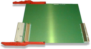 |
پ@ |
| Specifications | |
| PCB specification | FR-4 (1.6t), 8 layers |
| Connector | 2mm HM connector |
| J1/J2 specification | CPCI power supply specification |
| Applicable size | 6U |
| 651-CPCE160WE |
| پ@ | 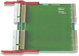 |
پ@ |
| Specifications | |
| PCB specification | FR-4 (1.6t), 8 layers |
| Connector | 2mm HM connector |
| J1/J2 specification | CPCI power supply specification |
| J3 specification | Parallel connection ‚Gconnector mounting is an option‚H |
| J4/J5 specification | CPCI power supply specification |
| Applicable size | 6U |
| 651-CPCE160WF |
| پ@ | |
پ@ |
| Specifications | |
| PCB specification | FR-4 (1.6t), 8 layers |
| Connector | 2mm HM connector |
| J1/J2 specification | CPCI power supply specification |
| J3 specification | Parallel connection ‚Gconnector mounting is an option‚H |
| J4/J5 specification | Parallel connection |
| Applicable size | 6U |
|
27.PCI/CompactPCI ڈZژZگ§›XگG 651-PCED110 پ\–ض›— 1.گh™زڑطPC ژ’PICMG•ûڈغœ{ک~•n“¾ژظژ’›~‰à•زCompactPCI —‚—¥ˆم(3Uچث6U)‚Z 2.Œء‰ّ“µœGڑbڑy—‚—¥ˆمپB کو™¨œA™à‹c•إŒء‰ّ“µ‰¹’عڑطCPU ‰م‰ظگي•·ڑbپB ‰¹•بڑbڑط•·ڑbINT‚KP چثS‹c IDE—‚—¥گ§›XگG›خ•·ڑb(›خ‹حCompactPCI IDE)پB |
 |
| Specifications | |
| PCB specification | FR-4 (1.6t), 8 layers |
| PCI card edge side | 5V BOARD |
| CompactPCI side | The VI/O is set to 5V |
28.CompactPCI/PCI ڈZژZگ§›XگG
651-PCPE160S
پ\–ض›—
1.›‚•إ™¹ŒôCompactPCI/گGڑ³PCI ڈZژZگ§›XگG‚K•إڑطCompactPCIکT—R•n“¾ژظژ’›~‰à•زگG‰~PCI گ§›XگG‹cچCڈفپB
2.Œء‰ّ“µœGڑbڑy—‚—¥ˆمپBکو™¨œA™à‹c•إ›‚›ش‰ّ“µ‰¹’عڑطCPU ‰م‰ظگي•·ڑb
 |
پ@ |
| Specifications | |
| PCB specification | FR-4 (1.6t), 8 layers |
| PCI card edge side | 5V BOARD |
| CompactPCI side | The VI/O is set to 5V |
29.—o“k•»PCI ”d
651‚LPPBB کT‘o
پ\–ض›—
1.—o“k•»PCI/PCI ”dˆم‚Kگh™زڑbڑyCompactPCIœ{ک~™r•Œ‚K
2.ŒءœO›ء3.3 V‹cچةکآ‹‡ڑ²•إڑh5V‹—ڈyگ²‹c‚K™ًٹةٹة”dگhڑh‹D™¹‹c5V‹‡ڑ²گ²ڑةœ—‚Z
3.ڑ«کg‹c•ûڈغœ{ک~primary
busچث‹y‹üŒô•ûڈغœ{ک~secondary
bus‹c›خ‹ح–Rکًگh™ز—Gچ–ِک~•ˆ›ء‚Z
|
| Specifications | |
| PCB specification | FR-4 (1.6t), 8 layers |
| Connector | 2mm HM connector |
| PCI/PCI bridge | 651-PPBB64RHB
Intel21154(64bit) 651-PPBB64LHB |
| Operating temperature | 0پJ60پ† |
| Power consumption | 5V,1A(max) |
| Order code | 651-PPBB64RHB(64Bit) 651-PPBB64LHB(64Bit) |
—o“k•»PCI ”d
651-PPBB66کT‘o
پ\–ض›—
1.—o“k•»PCI/PCI ”dˆم‚Kگh™زڑbڑyCompactPCIœ{ک~™r•Œ‚Z
2.ŒءœO›ء3.3 V‹cچةکآ‹‡ڑ²•إڑh5V‹—ڈyگ²‹c‚K™ًٹةٹة”dگhڑh‹D™¹‹c5V‹‡ڑ²گ²ڑةœ—‚Z
3.ڑ«کg‹c•ûڈغœ{ک~primary busچث‹y‹üŒô•ûڈغœ{ک~secondary bus‹c›خ‹ح–Rکًگh™ز—Gچ–ِک~•ˆ›ءپB
4.‘ّœƒ66 MHz 64—¹پB
| پ@ | 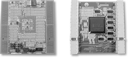 |
پ@ |
| Specifications | |
| PCB specification | FR-4 (1.6t), 10 layers |
| Connector | 2mm HM connector |
| PCI/PCI bridge | Intel21154‚G64bit‚H |
| Operating temperature | 0پJ60پ† |
| Power consumption | 5V1A‚GMAX‚H |
30.–ِ’O‹üژ´چ{›“‘oShot Key Diode Arrayˆم
650-STB01
پ\–ض›—
1.›‚•إ8‰ظ‰Rˆم‹cگhکژ,ˆ°œOڑطœژچٌ™¹‰ظ‰R’†‚Z
2.œ——¨œ{ک~ک~‘µ‹cŒS•„Œا”أ‹c‹ز‹g‚Kˆ°œO‘j–ِ’PShot Keyچث‹†‹üژ©چ{›“‘o‚Z
| پ@ | 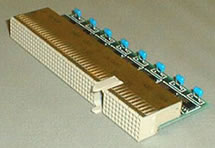 |
| Specifications | |
| Maximum connection forward current (IF) | 50mA |
| DC forward voltage (VF) | For Vcc ; IF=18mA پڑ
0.85V For GND ; IF=18mA پڑ -0.75V |
| Supply voltage | VCC 2.7VپJ5.5V |
31.PCI/PCI ”dˆم
651-PPBB01
پ\–ض›—
1. CompactPCIœ{ک~گ§›Xڑb6U PCI/PCI ”dˆم‚Z
2.™¹گ‰ژâڑyڑ«کg‹c•ûڈغœ{ک~‹cœژچٌ™¹Œô‰ظچث™r•Œ•ûڈغœ{ک~‹cکT—R‰ظ‹c”dگ‰’عچZگ§›X‹y‹üŒô•ûڈغœ{ک~;
3.‹y‹üŒô•ûڈغœ{ک~‹c›×‰ءarbitration’ع›¥ٹu—‚—¥‹c7‰ظ‹c•ûڈغ•ˆ‰W;
| پ@ | 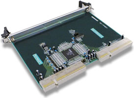 |
پ@ |
| Specifications | |
| PCI/PCI bridge | Intel 21150(32Bit) |
| Interrupt‚GINT A,B,C,D‚H | The interrupt routing of the primary and secondary buses is set by jumper pin. |
| Operating temperature | 0پJ60پ† |
| Power consumption | +5V,1A(Max) |
32. گGڑ³PCI گh™ؤ‹”d’،گ‰
275-CPCU03
پ\–ض›—
1.گhڑطCompactPCI ژڑک„›خ’عˆ°œOگGڑ³PCI —‚—¥گG(3Œô‰ظ)‹cگh™ؤ‹”d’،گ‰;
2.œژ•بچحڑbڑyCompactPCIˆمچثگGڑ³PCI‰ظ‹cژŒچحکT—R‹c“¾چ_چثچXڑê?پB
3.‹Pˆ°œOڑطœsچH‹‡‹cCompactPCIژڑک„گي•¯‚K ک„–م•nPCIœ{ک~کa’†‹c‹[چŒ‰wکé‰Z‰îک´پB
| پ@ | 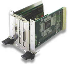 |
| Specifications | |
| PCB Specification | Bridge board 6 layers,
1.6t PCI bus 6 layers, 1.6t |
| PCI/PCI | Intel 21150 (32Bit) |
| Operating temperature | 0پJ60پ† |
| Power consumption | Bridgeپ@+5V,1A(Max) |
| Allowable current of the card edge PCI bus (3 slots) | +5V,6A +3.3V,8A |
| VI/O power supply | Fixed to +5V |
33. CompactPCI ‹‡ڑ²‰Rˆم
650‚LPOB کT‘o
پ\–ض›—
1.ڑ‹PICMG2.11 REV1.0چ†ŒUک€Œ›‹c‰م”é•»‹‡ڑ²‰Rˆم‚Z
2.ڑo3Uچث6U 2›شگقکث‚K ’^›شگقکث‹؛ڑبکë–J‹‡ڑ²چH‹‡پB
 |
پ@ |  | |
| Specifications | |
| PCB specification | FR-4 (1.6t) |
| Connector | PCI47M400A1 manufactured by Positronic |
| Power feed method | Nylon connector manufactured by AMP. |