![]()
| | 日本語 | English | 中文 | |
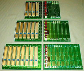
| Backplane PICMG Rev1.0 650-CPCI Family |
■Features
- There are 2 types of system slot configuration (8slots only), namely, one right-side configuration and the other left-side configuration, and there are 3 types of the number of slots, namely, 4 and 6, and 8 slots.
- All signal lines are arranged in the inner layer and the characteristic impedance is set to 65Ω.
- The power supply for I/O buffer (V I/O) can be set to a supply of +5V or +3.3V according to the system.
- Only the routing of INT, A, B, C and D is based on the REV2.1 specification.
 |
| Specifications | ||||||||||||
| PCB specification | FR-4 (3.2t and 4.6t) | |||||||||||
| 8 layers and 10 layers | ||||||||||||
| Power feed method | Screw terminal and faston terminal | |||||||||||
|
||||||||||||
| Backplane Pin Assignment Table | Backplane Pattern Connection Specification | |
| Order Code Table | |||||||
| Order code | No.of slots | System slot | L | P | S | t | No.of layers |
| 650-CPCI04R | 4 | Right side from the front face | 94.40 | 60.96 | 60.96 | 3.2 | 8 |
| 650-CPCI06R | 6 | Right side from the front face | 135.04 | 101.6 | 101.60 | 3.2 | 8 |
| 650-CPCI08R | 8 | Right side from the front face | 175.88 | 142.24 | 142.24 | 4.6 | 10 |
| 650-CPCI08L | 8 | Left side from the front face | 175.88 | 142.24 | 142.24 | 4.6 | 10 |